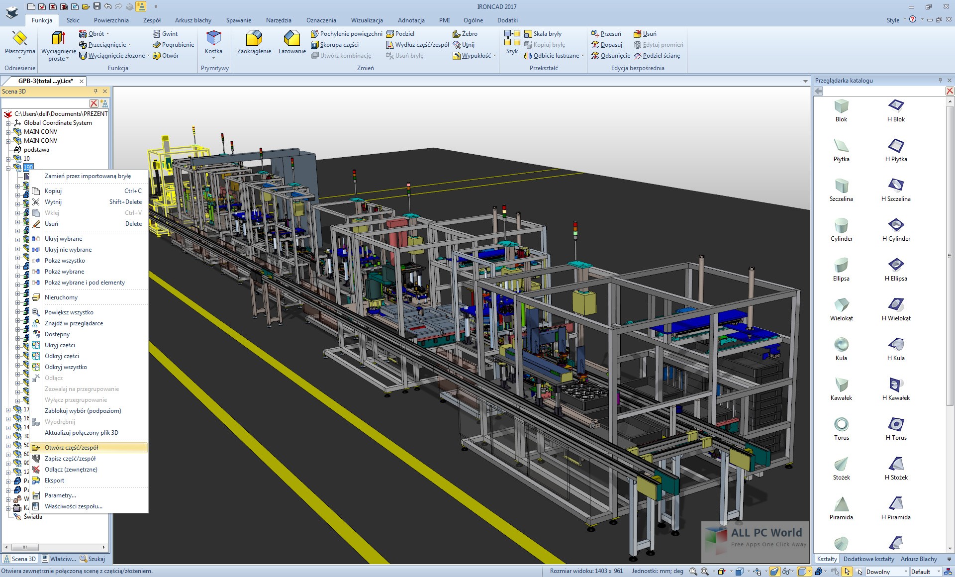

That make heavy use of plates and cylinders without drawing sketches.To scale an entire assembly model, it is possible to scale each part independently, however this could be extremely tedious for an assembly with a large.IRONCAD DRAFT provides various cursor interactions to provide a fluid and efficient design environment. The “catalog” has various shapes and materials, and it is possible to design automatic machines, equipment machines, jigs, etc. Step 5: And these are the. Step 4: When Large Assembly Mode in On, a message appears on the Status Bar. Step 2: You can set the Large Assembly Mode preferences by clicking Tools -> Options Step 3: Click on the Assemblies option and set your preferences.
Direct ediƟng of parts is also possible. Saving a model design in STL format: Open the model design in IronCAD.After conceptual design and detailed design in one file, parts / assemblies can be saved externally with links.You can create and disassemble assemblies with the touch of a button.The assembly structure can be freely edited from the history.③ Easy to allocate TriBall can move, copy and position any objects in the 3D scene.Complex positioning operation is possible withoutTriBall can be use to position objects :Shape, part, assembly, TriBall body, section figure, 3D curve, surface, joint point, face, light, camera, texture, contour, cut surface, animation pass etc④ Support Large Assembly Mode Tens of thousands of assemblies can be manipulated smoothly without suppressing parts. The procedures for doing so are described below. Tip: When working in assembly mode, you must save each of the component parts as individual STL files. In addition, standard navigation can be set to orthogonal, polar axis and three-view navigation-aided drawing methods.②Crisp concept file structure IRONCAD has the same file extension for parts and assemblies, so file management and conceptual design are smooth.Note: IronCAD can export in many file formats depending on your geometry.

Can be easily createdInterference of compoments by assembling and positioning constraintsSimulate motion by animation. You can edit individual shapes from the history afier the boolean creationMechanical parts such as bolts, taps, special holes, bearings, springs, gears etc. You can create a Union/Subtraction/IntersactionBoolean. The created surface can beParts. It is also possible to reference existing partsAnd the surfaces of an imported model.

Ironcad Large Assembly Mode Update Automatically When
Property information of 3D model can also be output to BOM for creating assembly and parts drawings.Dimensions, tolerances, notes, and symbols necessary for creatingMachinery drawings. 2D contents will update automatically when the 3D model is changed. It is useful for creating photorealisticProjection drawing can be easily created (.exb 2D file extension). Support for 2D flatPattern drawing, 3D conversion and bending.3D environments can be shown realistically by seƫng exposure, shadows, background, etc. Parts created by shelling and imported parts without history can be unfolded.
Output to EXCEL is also possible.Please contact us if you need assistance. BOM corresponds to both 3D scene and 2D drawing. It is possible to drastically reduce the time and effort to fill in the dimensionsYou can automatically create parts lists and item numbers associated with parts and assemblies.


 0 kommentar(er)
